Changing the Technics 1200 LEDS from Red to Blue
This job requires a number of tools, a medium amount of technical skill and lots of patience. Please remember not to force anything as this may cause damage to the parts that need to be removed.
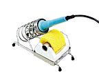
Tools
#2 Phillips Screwdriver, Precision Screwdriver set, Soldering Iron, Solder wick, Solder.
![]()

Parts
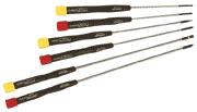
6 BLUE Round LED's (5mm). The power/strobe light requires four and the 33/45 switch requires 2.
![]()
1 BLUE Square LED (2mm X 5mm). This is a hard part to find. Its a small sqaure LED that fits into the pitch control to indicate zero pitch.
Now these parts are hard to come by and are costly as compared to Red, Green, or Yellow LED's. I paid $4 for each on at a local electronics store. I had to order the square LED online at Dialight

Step One:
Remove the rubber bottom of the turntable. This is done by removing all the screws, including the 4 screws under the four foot posts, and then the foot posts themeselves. You will need a Phillps #2 screwdriver for this. The foot posts come off by turning them counter clockwise. I usually leave the turntable upside down on its dust cover. REMEMBER TO REMOVE THE PLATTER, SECURE THE TONEARM, AND REMOVE THE 45 PLUG BEFORE YOU TURN IT OVER!!
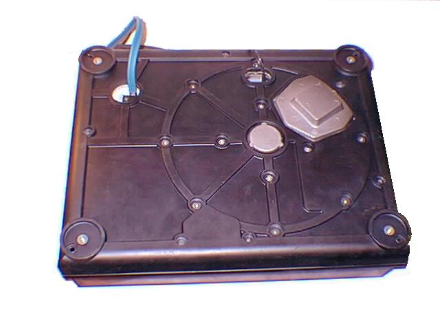
Step Two:
Once you have the bottom removed you will need to shift your attention to the bottom right corner of the turntable. This is where the circuit board is that contians the power and 33/45 switches. There is 4 screws holding the circuit board down, they are all the same color (black). 3 of the screws are at each corner and the the fourth is in the center. There is only one other screw (this one is usually a different color like broze or silver), you can remove that as well, or wait until later on, but it does not have to be removed to get the circuit board removed. Once the screws are removed carefully pull the circuit board out, do not pull too hard as it is attached still by some wiring which we are going to leave attached. Once you have it out, flip it over and have a look. You will see the power switch. We need to get that cover off.
Step Three:
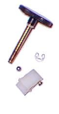
Now, looking on the backside of the circuit board (the side without the switch), you will see a small clip holding the power knob in place. Using your precision screwdriver, remove the clip. Once the clip is off you can remove the white switch mechanism, at which point the power knob will fall through. There is also a small bearing under the white switch. Be careful not to loose it or the spring that holds it in place. Keep these parts somewhere handy so you don't loose them, they are small. Now turn the board over to the side with the switch. You can now see into the power switch now that the knob is off.
Pictured below, Power Knob, Retaining clip, Ball Bearing, and White plastic switch knob.
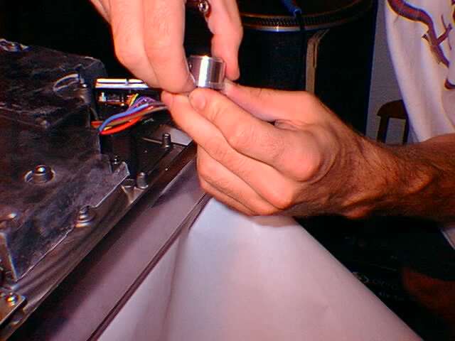
Step Four:
This part is tricky. The silver casing for the power knob is held on by two clips located on the inside, and there is usually some sort of adhesive holding it in place as well. To get this off you can use a precision screwdriver to push each of the clips on the inside ONE at a time. Work the knob around very slowly and carefully. Even after the clips have been disengaged you will still have tension on the knob. Pull it off carefully. Once the casing is off you have access to the LED board.
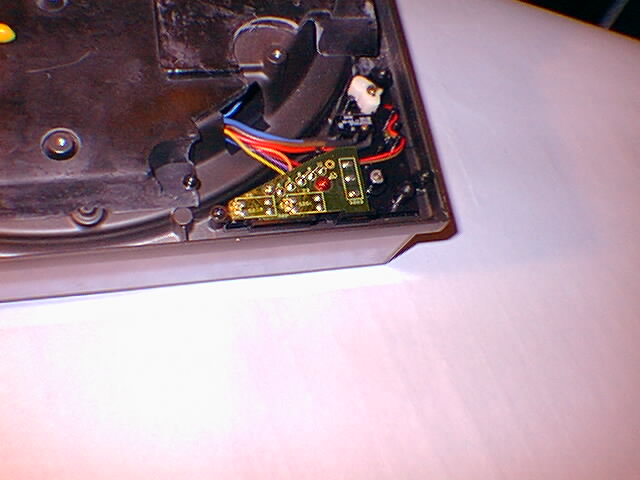
LED board, these are what you are after
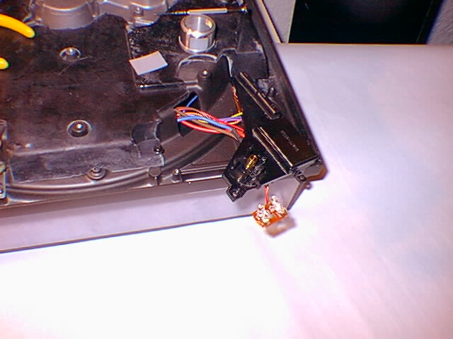
Step Five:
Remove the white filter. The wiring for the LEDs is wound around the circuit board. Unwind the wires and this will allow you to lift the LED board up off the main circuit board housing. You are going to remove each of the LEDs on this board. Place the LED board somewhere solid nearby (probably on the underside of the turntable. Remove the LEDs by using solder wick or a solder sucker. Using Solder wick is very simple. Hold the wick on the bottom side of the circuit board where the LED posts come through and are attached by the solder. Using the soldering iron, press the wick onto the solder joints until the solder heats up and is absorbed into the wick. Repeat the process for all the posts. When you go to pull the LEDs out heat up the posts a little, sometimes there is some solder residue left and can make it tricky getting them out.
Step Six:
Now hopefully you noticed that there is a small plastic space around one of the two posts on each LED. Save these. Now, LED's have a correct polarity. It is marked on the circuit board. If you look closely at the LED, it has a flat side, and a round side. Simply line up the flat side to be the same as the flat part of the diagram on the circuit board. The diagram looks like this..
The flat side of the LED also has a shorter leg if you can't tell by looking at it.
Step Seven:
Solder the new LEDs in place. Making sure once again they are in correctly. Once you have the LEDs soldered in you are basically done. Put the LED board back in place, rewrap the wires, replace the white filter, and put the silver housing back on. Now, you have to be kind skillful to get the power knob back on. First put the knob through the center hole and make sure you have the labeling (power/on/off) facing the right way. You'll notice the Power knob shaft has a flat side to it, and the white plastic switch you removed also has a flat side to the hole. Now, replace the spring in the white plastic part, putting the white part onto the power knob shaft (boy, this is kinda hard to explain.!) Now, once you have it in place you will need to get the ball bearing on top of the spring before you push the white part down all the way. Be patient, I know you can do it. Once you have that together replace the tension clip and you're all set. Now, if you're not going to replace the 33/45 lights, put the circuit board back in place and screw it down. Replace the rubber bottom and you're done. Its a good idea to try it out before you put all the screws into the base. Anyways, Now you can replace the 33/45 lights.
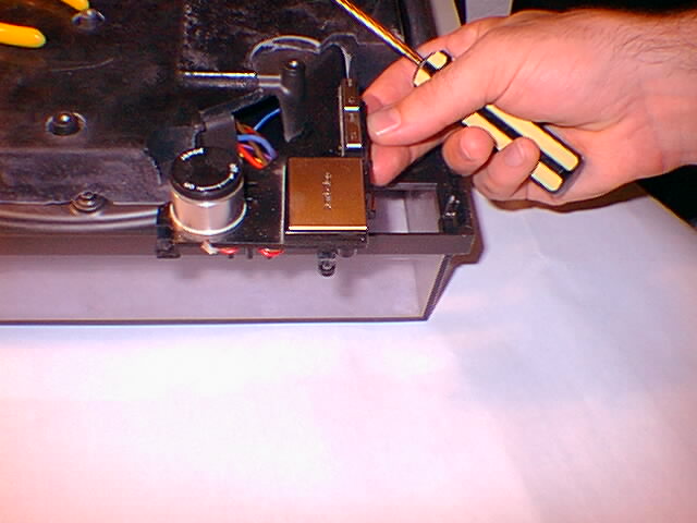
Step Eight: Replacing the 33/45 LED's
Now, if you didn't remove the odd screw mentioned before, do it now. You can now lift a smaller circuit board back and out from the main one. Once its off you'll immediately see the 2 LED's you're after. Following the same desoldering techniques mentioned before, remove the two LEDs. The rules are the same and this part is A LOT easier than the first one. The only thing different is that if you use 5 mm LEDs here instead of the 3mm currently installed, you will need to replace the LED's without the white spacer under the 3mm LEDs. The 5mm LEDs are a lot brighter however, so I choose to use them instead of the 3mm.
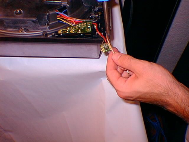
Step Nine: Replacing the Pitch LED
This LED is easy to replace as well. Simply remove the two screws holding the pitch housing and circuit board down located on the very left side of the turntable. Once you have the screws off you can lift and flip over the pitch housing. Immediately you'll see the little green square LED. Desolder it and replace it. Simple.
by Chris Robin